I. Introduction
Chip control is an important issue that needs to be solved in the production of metal cutting. Poor swarf can damage the operator, affect the surface quality of the machined parts, damage machine tools and tools, increase auxiliary work hours and affect productivity. With the development of various automation technologies such as CNC, FMS, and CIMS, chip control issues have become more important because poor chipping will prevent automated production lines from functioning properly. One of the basic problems with chip control is to reliably break the chips. The most common method currently used is chip breaking with chipbreakers. Chip breaking chip breaking is the principle of using the material to be hardened and impacted and crushed to achieve the breaking strength. Due to the important role of the indexable insert chip breaker in chip handling, cutting resistance, tool life, machining accuracy, etc., the groove shape of the chip breaker has been continuously improved in the past two decades, and a linear blade has been developed. The chip-breaking groove combined with the curved edge, the curved edge and the curved surface, the multi-face type convex, the concave type and the like, the groove surface becomes more and more complicated, and the chip breaking performance is also continuously improved. The development of a new chip breaker type is one of the effective ways to develop new blades and improve the cutting performance of the blades.
|
|
| figure 1 | |
|
|
| figure 2 | |

Second, the improved design of the chip breaker groove
Chip breakers can usually be divided into chipbreakers for finishing, semi-finishing and roughing according to their application. In order to improve the cutting performance of the carbide-type indexable insert with the insert groove type M5 in rough steel, stainless steel and cast iron, and to improve the service life of the insert, the M5 type chipbreaker has been improved. Figure 1 shows the chipbreaker geometry before and after the improvement. The key to the improved design is the chipbreaker geometry with a combination of negative chamfers and dimples. Because the chips flow out from the rake face of the tool during the cutting process, the underside of the chip and the groove bottom of the chip breaker are strongly rubbed, which generates a large amount of heat, and the cutting heat is continuously transmitted from the chip to the blade, causing the blade to wear. As shown in Figure 2, a pit is cut at the bottom of the chip breaker to minimize the contact area between the blade and the chip bottom layer to reduce blade wear and increase blade life. The negative chamfering of the 5° positive rake angle is designed to reduce the cutting forces generated during the cutting process.
Third, the improvement of cutting performance before and after the improvement
- Cutting force comparison
- Tool life comparison
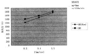
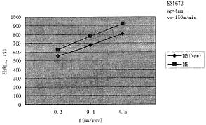
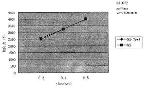
The improved M5 (New) type chipbreaker adopts a negative chamfer with a positive rake angle of 5°. The design of the negative chamfer is the main factor affecting the cutting force, mainly the influence of axial force and radial force. Fig. 3, Fig. 4 and Fig. 5 show the comparison data of the cutting force components when the cutting workpiece material is SS1672 at V c = 150 m/min and a p = 4 mm before and after the improvement. The results show that the axial and radial forces of M5 (New) and M5 are reduced by 8% to 10% and 12% to 14%, respectively, when cutting steel and stainless steel, and the tangential force is basically unchanged.
|
| ||||||||||||||||
|
| ||||||||||||||||
|
|
The improved design of the M5 type carbide indexable insert is mainly to improve the cutting performance when processing steel, stainless steel and cast iron. Table 1, Table 2, and Table 3 are the comparisons of tool life between M5 and M5 (New) in turning steel, stainless steel, and cast iron under the same cutting conditions. Table 1 shows the outer circumference of the steel wheel of the C45 turning workpiece; Table 2 The workpiece material for turning is the inner hole of the cast iron hub of GGG50; Table 3 is the outer surface of the stainless steel flange for turning the workpiece material to F51. Obviously, compared with M5, M5 (New) has greatly improved tool life under the same cutting conditions.
Fourth, the conclusion
By improving the cutting performance of the indexable inserts before and after, under the same cutting conditions, the chipbreaker groove type with negative chamfering and pit combination is improved, and the service life of the blade is greatly improved.
Smd Led Strips,Led Flexible Light Strip,Mini Pcb Light Strip,High Density Led Light Strips
Top Lighting International (HK) Co., Limited , https://www.topled-group.com